This section describes the process of configuring Net Inspector workspace. Workspace is a conceptual environment that allows you to model the monitored network according to your preferences. It lets you group devices in maps and structure such maps in a hierarchical manner within user views, e.g., to depict a logical topology of the managed network.
A user view contains one ore more maps and devices on maps. User views differ in respect to what devices they contain and how devices are grouped and hierarchically structured. A user view can contain either all devices registered with Net Inspector (e.g., an administrator user view), or any subgroup of devices (e.g., user views assigned to users with limited access rights). One can create different user views for different users. See also section About Users, Access Rights and User Views. For instructions on how to create a new user view and assign it to users, see the section Configuring User Views.
All procedures described in this topic and subtopics require using the Map View frame in Configuration Mode.
In order to configure the workspace, i.e., add maps to a user view, add devices to maps, add graphic objects and text to maps, edit or reposition objects on the maps, remove objects from maps, etc., you need to switch the Map View frame in the Devices page into Configuration Mode, as described in this section.
Note: Only users with administrator access rights are permitted to use the Map View in Configuration Mode..
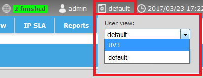
From the User view drop-down list in the upper-right section of the Net Inspector header, select the user view you wish to edit (see the figure below).
Figure: Selecting the user view
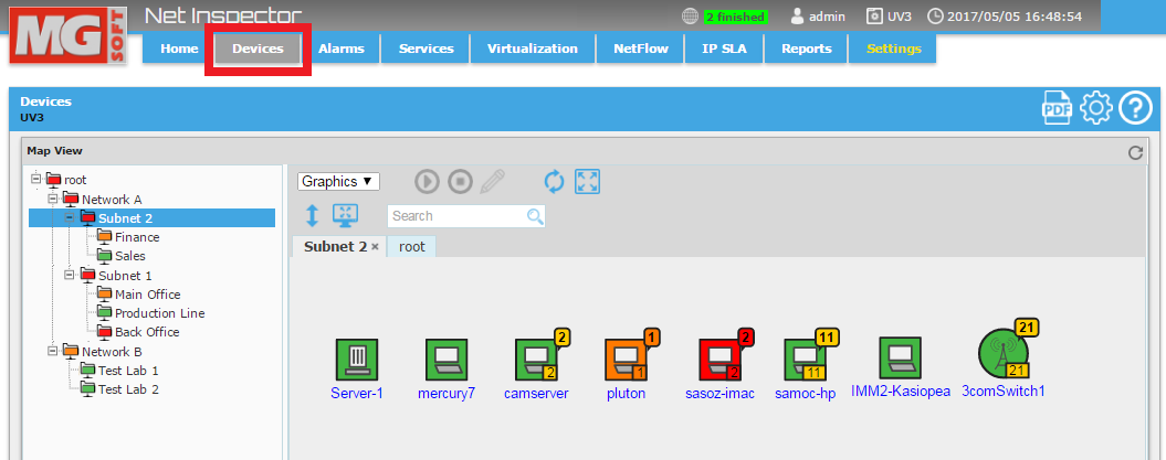
Click the Devices tab in Net Inspector header to display the Devices page (as shown below).
Figure: Selecting the Devices tab
In the upper-right section of the Devices frame, click the Configure button (as shown in the figure below) to enter the Configuration Mode.
Figure: Switching into map Configuration Mode
![]()
The Devices page with the Map View frame in Configuration Mode appears, as shown in the image below.
Figure: Map View frame in Configuration Mode
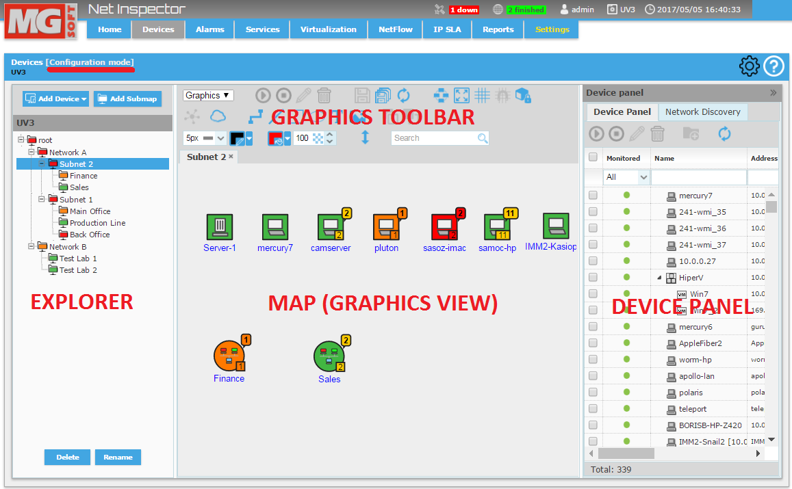
The Map View frame in Configuration Mode has several sections not available in Normal mode, as follows:
The Explorer Panel on the left side lets you configure a hierarchical structure of maps within a user view and lets you select a map to view its contents in the central section (Map frame). It contains buttons for adding devices and adding submaps to the selected map (upper section) and the buttons that let you rename and delete the selected map (lower section). Explorer panel also provides a quick overview of device statuses by propagating the color of the most severe device status up the hierarchical tree to the root map.
The Map View panel in the central section displays the contents of the map currently selected in the Explorer panel. It offers two views:
Graphics view - displays the contents of maps in a graphical manner, by showing device and submap icons, and optionally, graphic elements (lines, connections, rectangles, bitmaps, etc.). For more details, please refer to the Viewing Devices in Graphics View topic.
Details view - displays detailed information about devices and (sub)maps in form of a table. For more details, please refer to the Viewing Devices in Details View topic.
Graphics toolbar in the upper-middle
section is used for adding graphic objects (lines, connections, rectangles,
ellipses, images, etc.) and text to maps. In addition, it is used
for setting the properties of graphic objects (color, line width,
etc.), and for arranging icons and graphic objects in the Map View
frame (relayout, snap to grid, bring to front, send to back, etc.).
Furthermore, the Graphics toolbar is used for saving the layout of
maps, for locking graphic objects on maps, etc. For description of
these operations, please see the Adding
Graphic Objects, Images and Text to Maps topic.
The graphics toolbar in the Configuration Mode contains more icons
than the toolbar displayed in the Normal mode. Place a mouse cursor
over an icon in the toolbar to view its description in a tooltip.
Device Panel is displayed in the right portion of the frame. It contains two tabs:
Device Panel - it displays all devices that exist in Net Inspector and lets you add them to the workspace, as described in the Adding Devices to Submaps from Device Panel topic.
Network Discovery - it contains all configured discovery operations and devices discovered during each discovery operation. Once can either automatically or manually add discovered devices to a map. For more information, please consult the Adding Devices by Using Network Discovery topic. Note that all devices listed in Network Discovery tab exist also in the Device Panel tab.
You can use the Map View in Configuration Mode to perform typical workspace configuration tasks, as follows:
Add maps to a user view, as described in the Adding Submaps subtopic.
Add devices from Device Panel to maps, as described in the Adding Devices to Submaps from Device Panel subtopic. See also Adding Devices to Net Inspector topic.
Connect devices on maps with connection lines, as described in the Connecting Devices subtopic.
Add graphic objects, bitmap images, cloud objects and text to maps, as described in the Adding Graphic Objects, Images and Text to Maps subtopic.
When
you have completed configuring the workspace, click the Configure toggle
button (![]() ) in
the upper-right section of the Devices frame to exit the Configuration
Mode.
) in
the upper-right section of the Devices frame to exit the Configuration
Mode.
Subtopics:
Adding Devices to Submaps from Device Panel
Adding Graphic Objects, Images and Text to Maps
See Also:
Adding Devices to Net Inspector